The dimensions of the television are:
16 1/4 inches wide at the bottom
15 inches high, including the feet at the four corners
15 1/4 inches deep
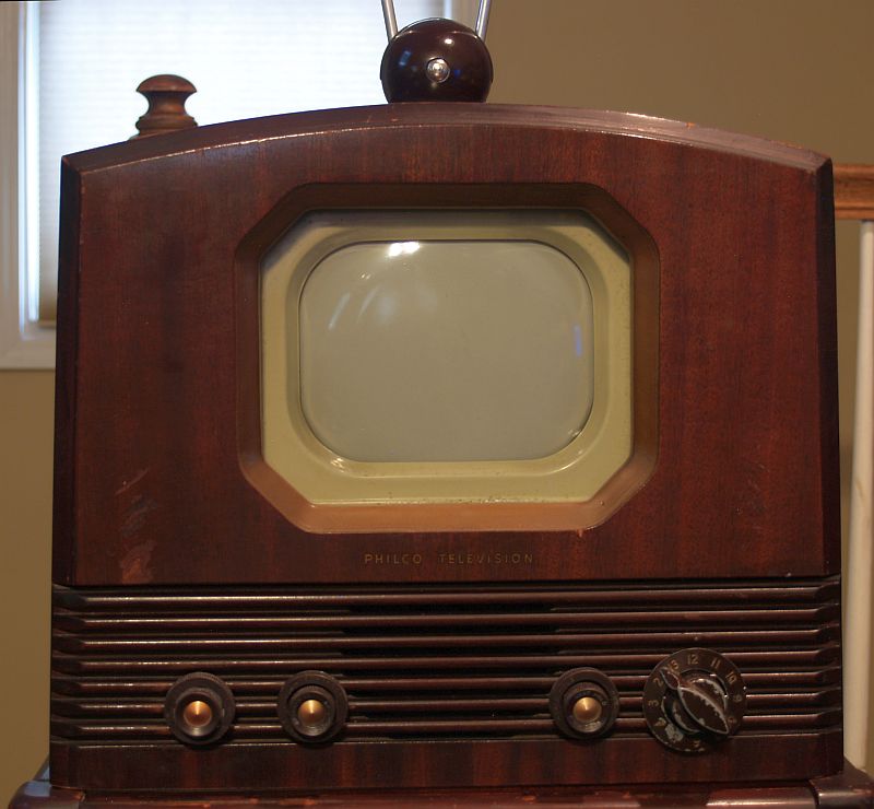
The inside dimensions of the escutcheon that define the image area are:
6 inches wide
4 1/2 inches high
Thus, the image area is quite small. A magnifier was often used to enlarge the image for viewing further away.
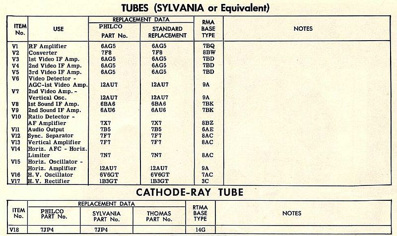
Below is a picture of the model and tube layout tag inside the cabinet.
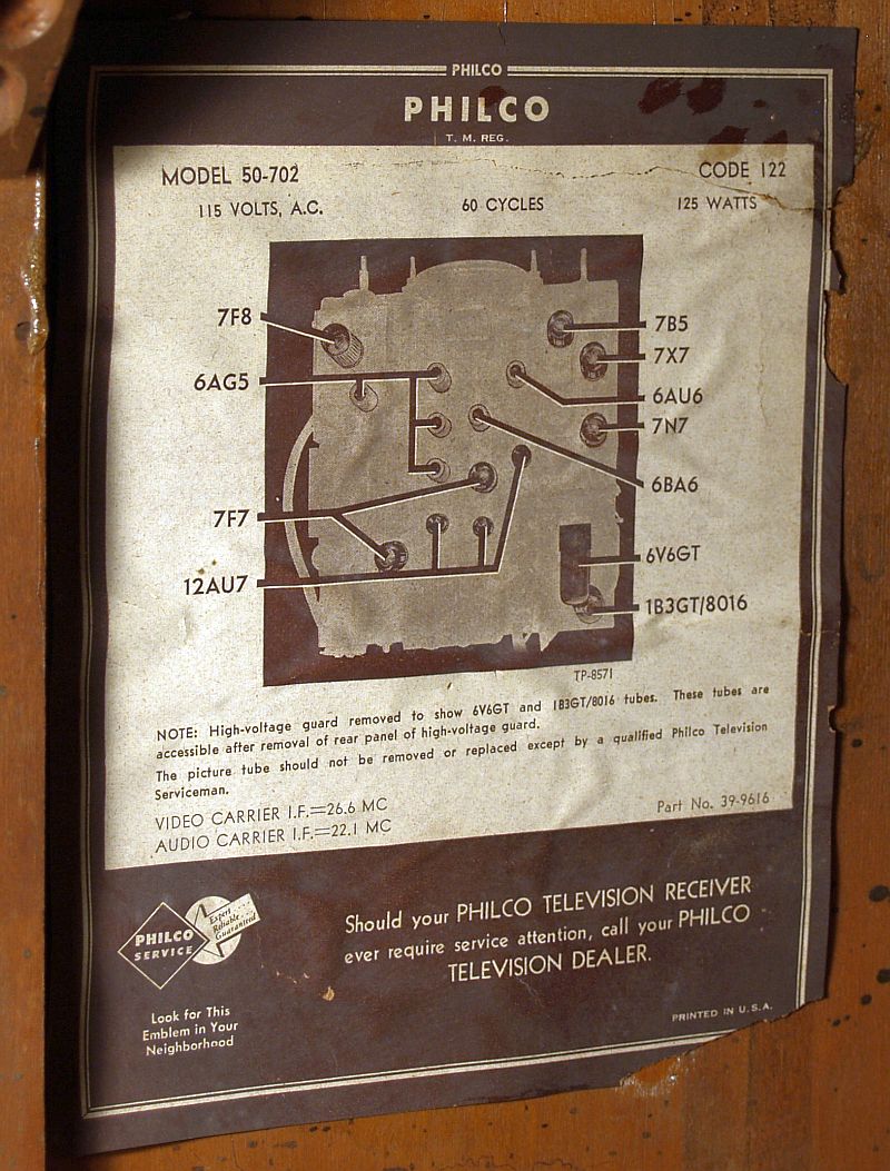
Note that the video carrier Intermediate Frequency (IF) is 26.6 MHz and the audio carrier IF is 22.1 MHz. Later televisions increased these IF's to around 45 MHz.
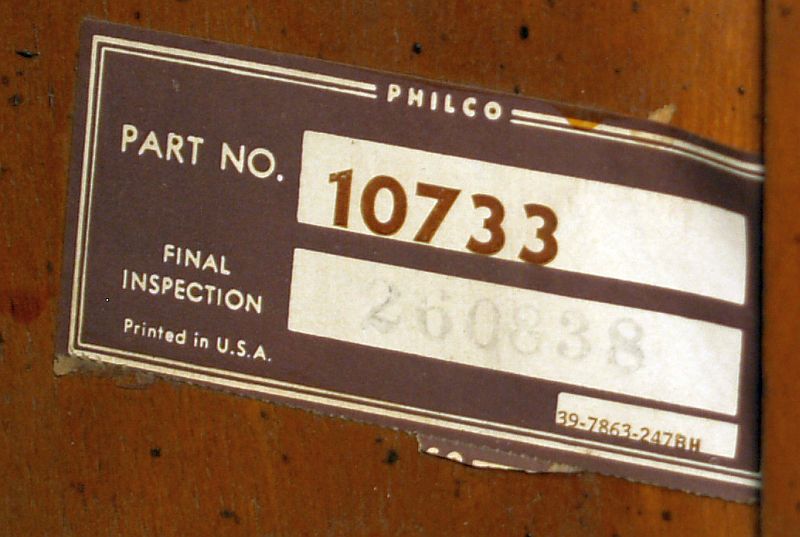
Below is a picture of the inspection label inside the cabinet.
The picture below shows the controls on the front of the receiver as depicted in SAMS Photofact Folder 7 of Set 140.
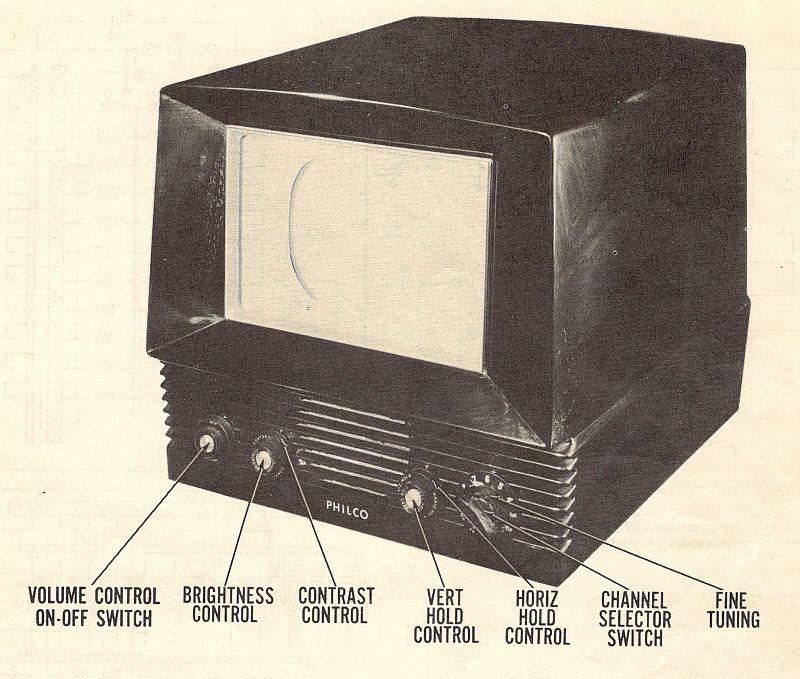
The controls on the front panel include:
| Volume Control & On-Off Switch |
| Brightness Control/Contrast Control |
| Vertical Hold Control/Horizontal Hold Control |
| Channel Selector Switch/ Fine Tuning Control |
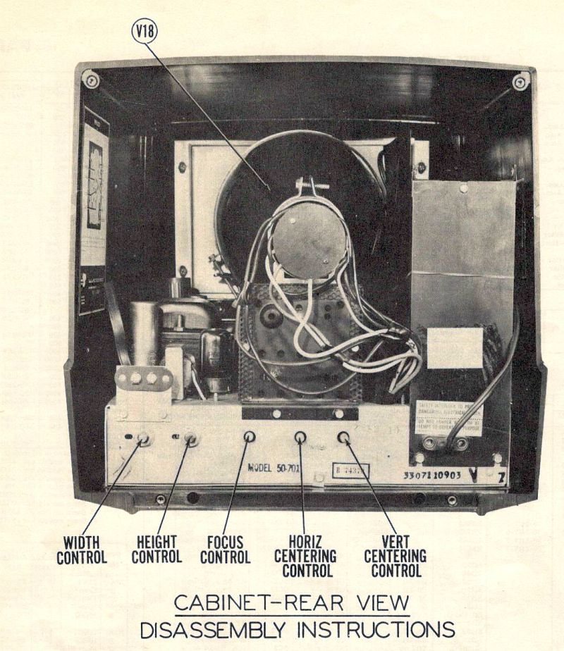
The picture below shows the controls on the rear of the receiver as depicted in SAMS Photofact Folder 7 of Set 140.
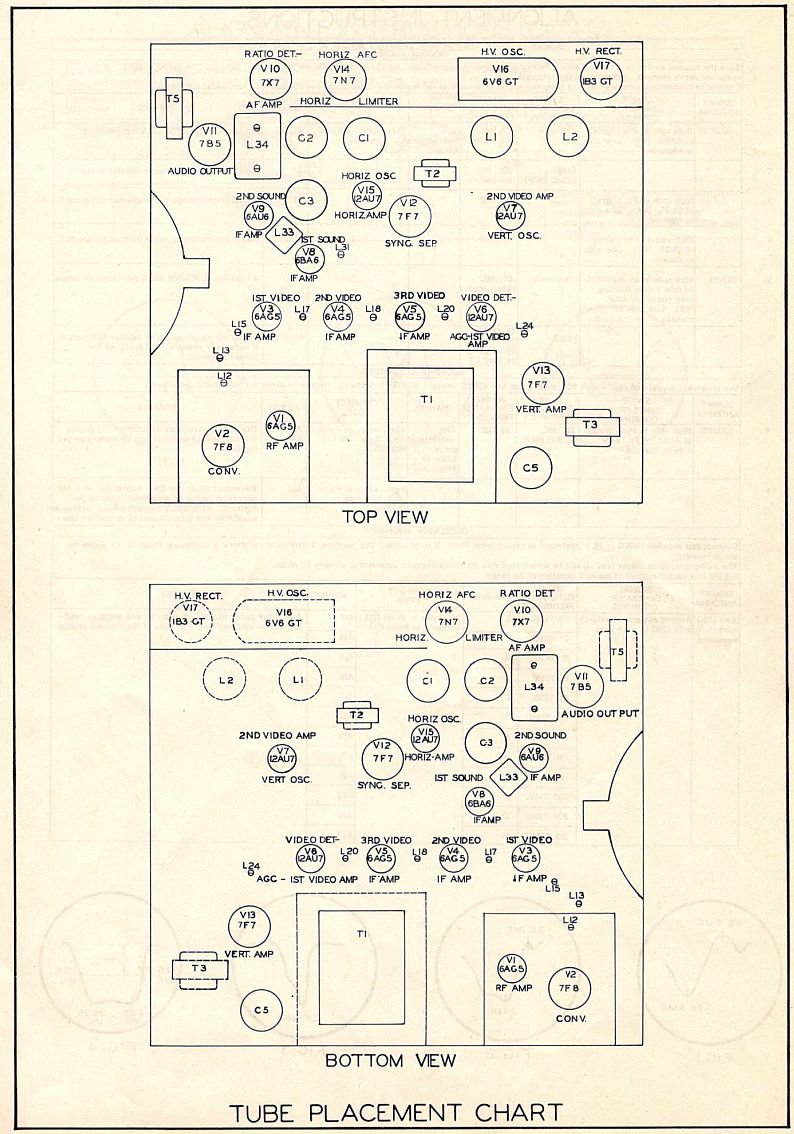
The picture below shows the tube layout as depicted in SAMS Photofact Folder 7 of Set 140.
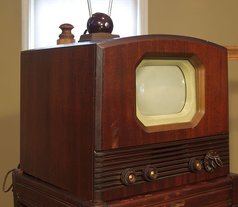
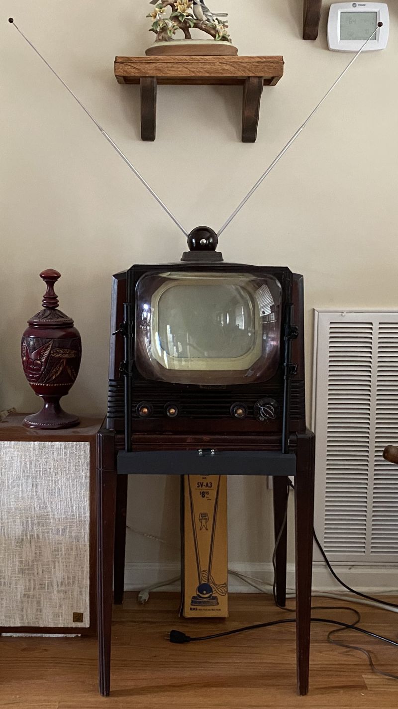
Below is a picture of the television when I received it.
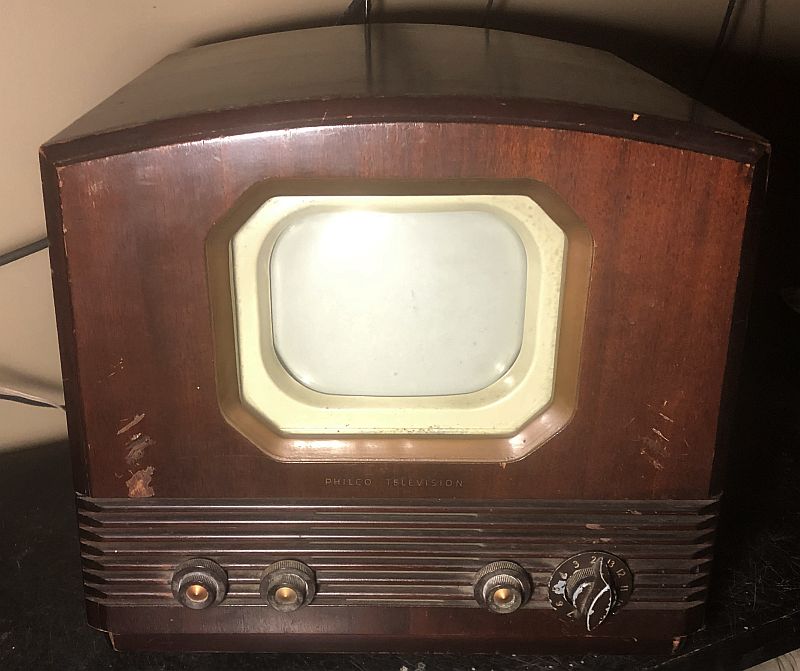
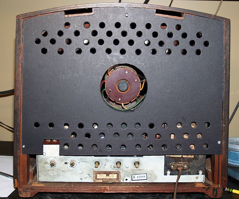
The cabinet was in fairly good shape with a few scratches and dings. The decal on the front is good shape and all knobs are present. Below is a picture of the rear of the television when I received it.
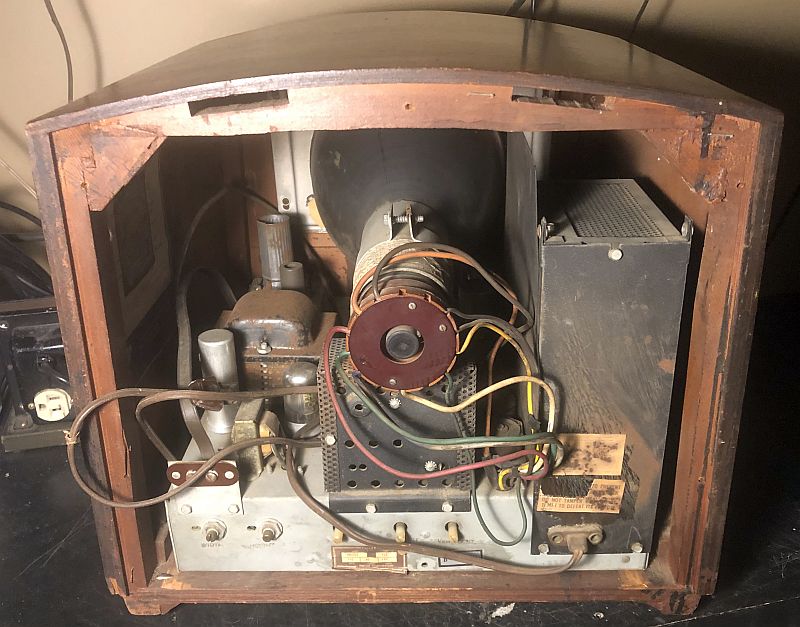
As you can see, the television looks is good shape; however, the back cover of the television is missing.
The picture below shows the top of the chassis when removed from the cabinet.
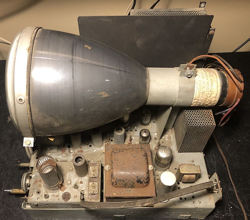
Everything looks in good shape except it is a little dusty.
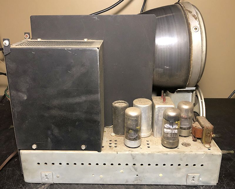
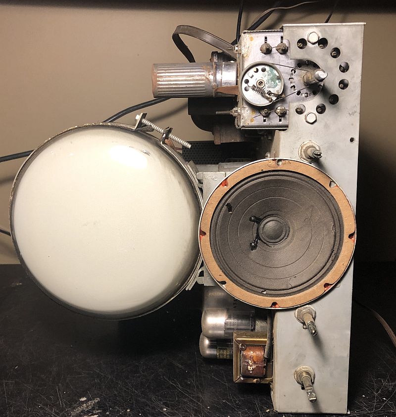
A picture of the high-voltage side of the side of the chassis is shown below.
The front of the chassis is shown below.
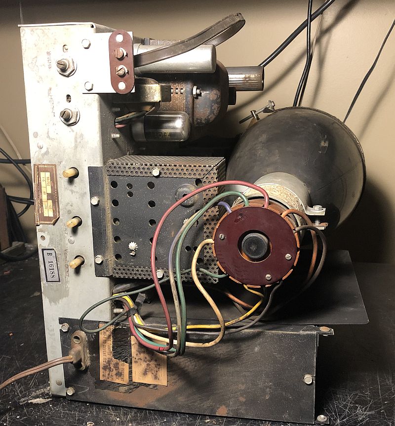
The rear of the chassis is shown below.
The bottom of the chassis before restoration is shown below.
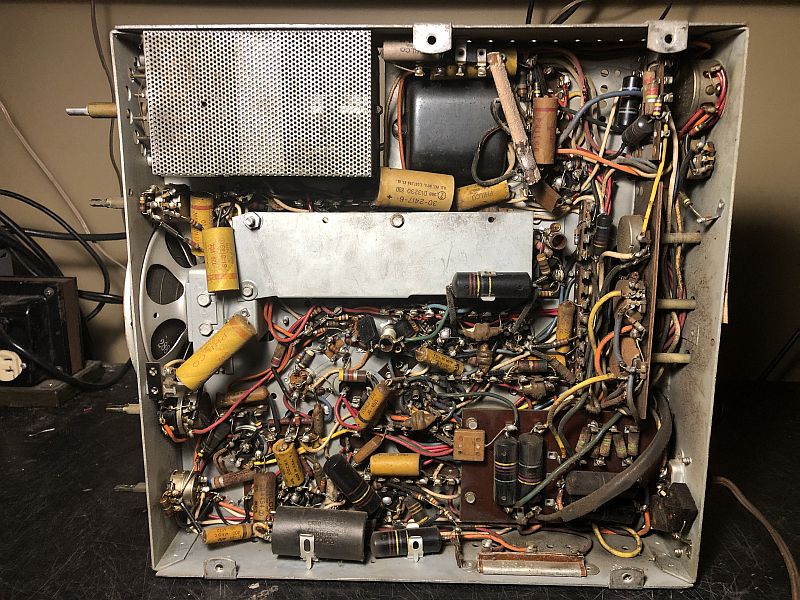
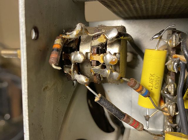
As you can see, no restoration had been done to the television as all of the original wax paper capacitors and "bumblebee" capacitors are all present. Note the power resistor at the top right of the photo above. That portion of the photo is enlarged below.
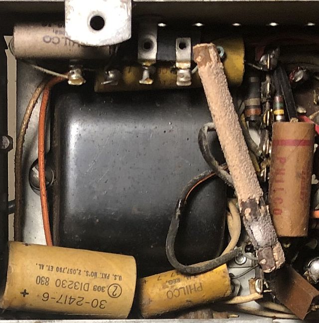
The power dual-resistor had apparently seen some excess heat as the covering on the lower portion was flaking off and upon closer inspection the lower portion appeared burnt and when I removed the resistor to replace it, the lower portion broke apart. Small pieces of the resistor covering flaked off and lodged behind the circuit board that contained the 1-M ohm resistors in the high voltage ladder network. After I had the television working, those pieces caused arching in the circuit board. I used compressed air to blow out all of those pieces and no arching is experienced now. I suspect the resistor overheated as a result of the shorted selenium rectifier discussed below.
Below is a picture of the two selenium rectifiers with their cage removed from the chassis and the cage cover removed.
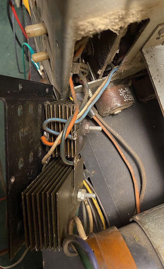
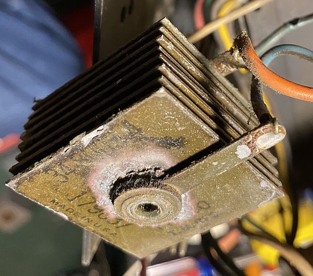
The smaller selenium rectifier shown below was shorted to ground.
In addition, two of the wires connecting to the selenium rectifiers were pressed against the rectifier fins and the heat from the rectifier over time melted the insulation. You can see the orange wire in the first selenium rectifier picture above pressed against the fins of one of the selenium rectifiers. I placed heat shrink tubing over those places in the wires.
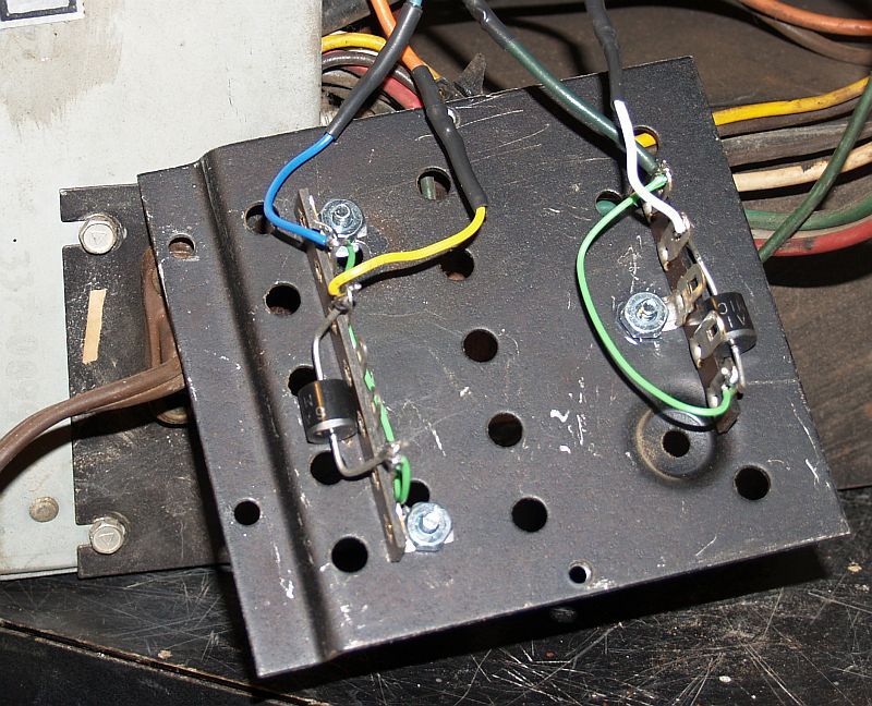
I replaced both selenium rectifiers with high-voltage silicon diodes. The new silicon diode replacements are shown below.
Below are pictures of the original high-voltage oscillator cage with its protective cover removed.
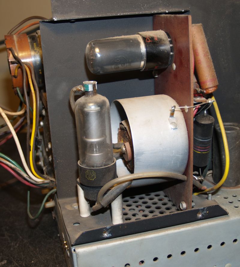
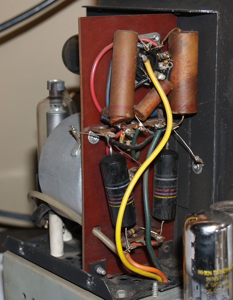
Note the wax paper capacitor in the upper left in the last picture above. Its lower end is almost out of its cylindrical package - indicating this capacitor is certainly bad. This capacitor is part of the resonant circuit for the high voltage oscillator that generates the anode voltage for the CRT.
I did not attempt to power up the television until I replaced all of the wax paper and "bumblebee" capacitors and the selenium rectifiers. Doing so would be a futile effort because of the high potential for defective capacitors and the complexity of the circuitry.
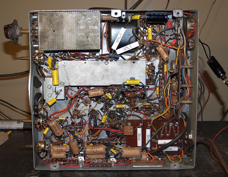
Below is a picture of the bottom of the chassis after I replaced all of the wax paper, "bumblebee," and electrolytic capacitors. The television has four multi-element electrolytic capacitors in cylindrical cans mounted on the top of the chassis. These capacitors are for power supply filtering and bypass/decoupling in several circuits. I replaced all of them with modern and much physically-smaller capacitors. I wrapped each in cardboard and noted on each the capacitance value, working voltage, and reference designator per the electrical schematic. Because of the limited physical space underneath the chassis, the cardboard sleeve is intended to prevent any accidental short circuits and the notations on the cardboard will help in future troubleshooting.
I did not place those new electrolytic capacitors in exactly the same location as the originals - the smaller packages allowed them in many cases to be placed closer to the circuits they were connected to. However, the original capacitor terminals were also used as tie points, so I had to be careful to maintain those connections when disconnecting them from the original capacitors. The picture below shows the underside of the chassis after replacement of all of the capacitors,and in a few cases, replacement of out-of-tolerance resistors.
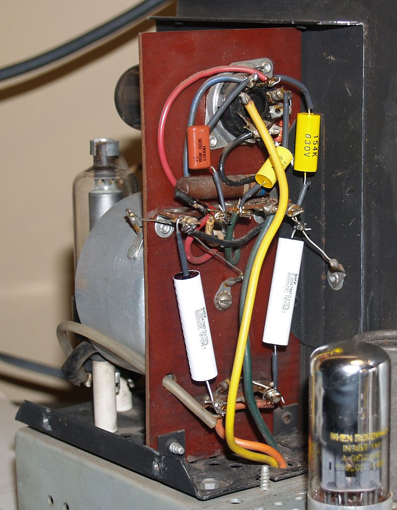
Below is a picture of the restored high-voltage cage.
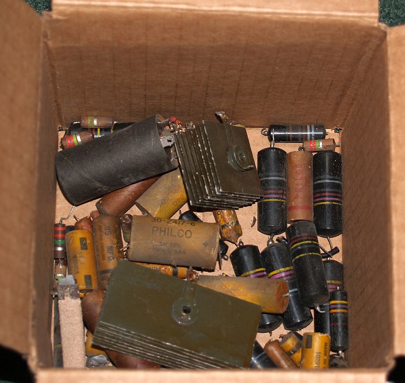
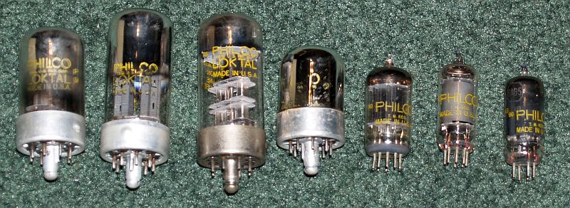
Below is a picture of a box containing all of the original resistors, capacitors, and selenium rectifiers that I replaced. Most all of the capacitors had the Philco name on them. Also below, is a picture of most of the original tubes I replaced. All of the tubes had the Philco name on them.
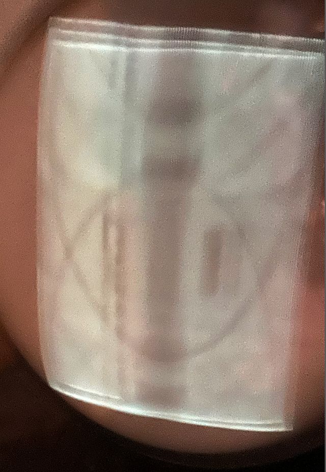
When I was comfortable that the restoration did not introduce any wiring errors, I slowly brought up the power with a variable transformer while monitoring the B+ voltages. I paused at about 50% and 70% and then slowly raised it up to about 90%. The raster shown below finally appeared on the screen showing the CRT (that is hard to find) is good. It takes a while after full power is applied for the television to come alive and begin working.
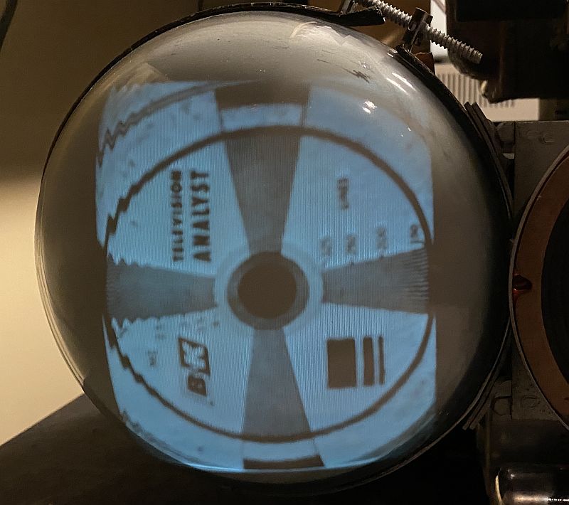
The television would not produce an image or sound from my B&K Television Annalist, but the raster would flicker and I could hear a faint tone when I adjusted the IF frequency on the Analyst. Then, I tested all of the tubes and found many of them weak or bad. I replaced the weak and bad tubes.
Replacing the tubes did allow the television set to process and display an image. The image is shown below.
I was able to sync the image in the vertical direction (horizontal in the picture) but not in the horizontal direction (vertical in the picture). The television was showing multiple images in the horizontal direction. It turns out the horizontal oscillator was running at about 22 kHz and not at the correct frequency of 15.75 kHz. Investigation into the horizontal circuitry revealed the actual circuit did not agree with the electrical schematic, including the modifications in the schematic noted as differences for "some models." The non-documented discrepancy was associated with a 10k-ohm resistor across the horizontal hold potentiometer. This resistor is not shown in the schematic. I theorized that the 10k-ohm resistor was selected by trial and error during assembly to accommodate the equivalent series resistance of the wax paper capacitor used for frequency determination in the horizontal oscillator circuit. I clipped out the resistor, and the television would synchronize in both vertical and horizontal, and the horizontal hold control was near the center of its range. The image below show the resistor after I clipped one end from the circuit.
The synchronized image after clipping the resistor is shown below.
I then tested the television to see if the tuner would convert RF to an image and sound. For this, I used an RF generator with both amplitude and frequency modulation. Amplitude modulation at 400 Hz will produce vertical bars across the image when the RF is centered at the visual carrier frequency. Amplitude modulation or frequency modulation will produce sound when the RF is centered at the aural carrier frequency. Several channels were not operating properly - especially those channels in the upper tier channels - channels 7 through 13. To investigate this situation, I removed the cover from the tuner. The uncovered tuner is shown below.
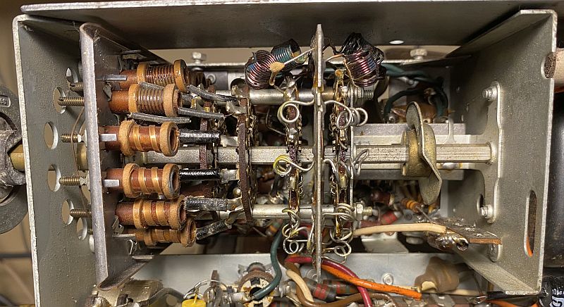
Changeover from the lower tier channels (channels 2 through 6) to the upper tier channels is accomplished by a slide switch moved by a cam plate. The cam plate and slide switch behind it is shown below in the right-hand side of the picture.
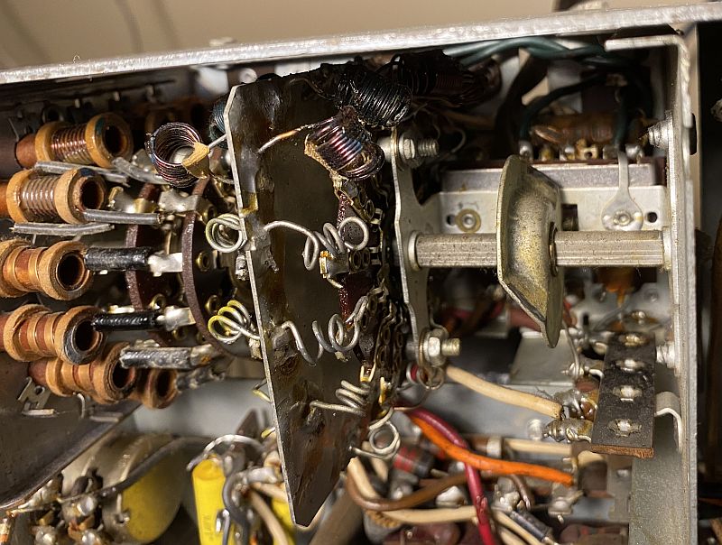
Changeover from the lower tier to the upper tier appeared to be implemented in an odd manner in this television. Changeover appeared to be accomplished going from channel 2 to channel 13 and from channel 13 to channel 2. One would intuitively think the changeover would be between channel 6 and channel 7. It turns out the cam plate had not been moved in a long time and would go in only one direction. After the lubrication set in, it works in both directions now and the tuner now works as expected.
I sprayed contact cleaner on all of the contacts on the tuner wafers and on the slide switch. There was a lot of oxidation and I had to use emory cloth to really clean some of the contacts. This effort brought the tuner back to life. However, all of the upper channels would receive video but no audio. It turns out that the local oscillator frequencies for all upper tier channels was about 2 MHz high, placing the downconverted audio outside the intermediate frequency (IF) bandpass filter. I used my frequency modulated RF generator to retune all of the upper tier local oscillator coils to bring the signals to within the tuning range of the fine tuning control of the television. However, after a while, I had to retune the channels (in particuar Channel 12, the one I am using) back to its original position becasue the oxidation was further removed by recent use.
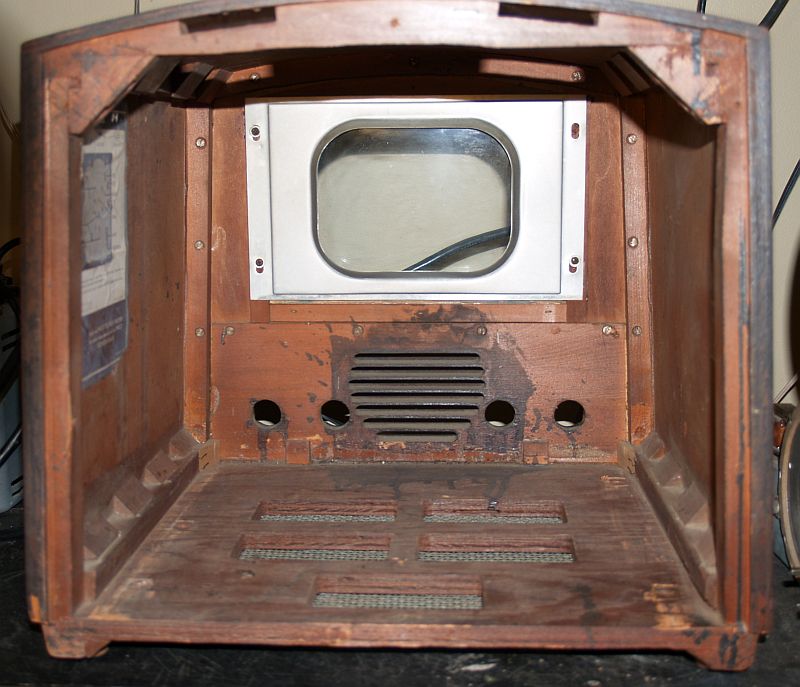
Below is a picture of the inside of the cabinet with the chassis removed.
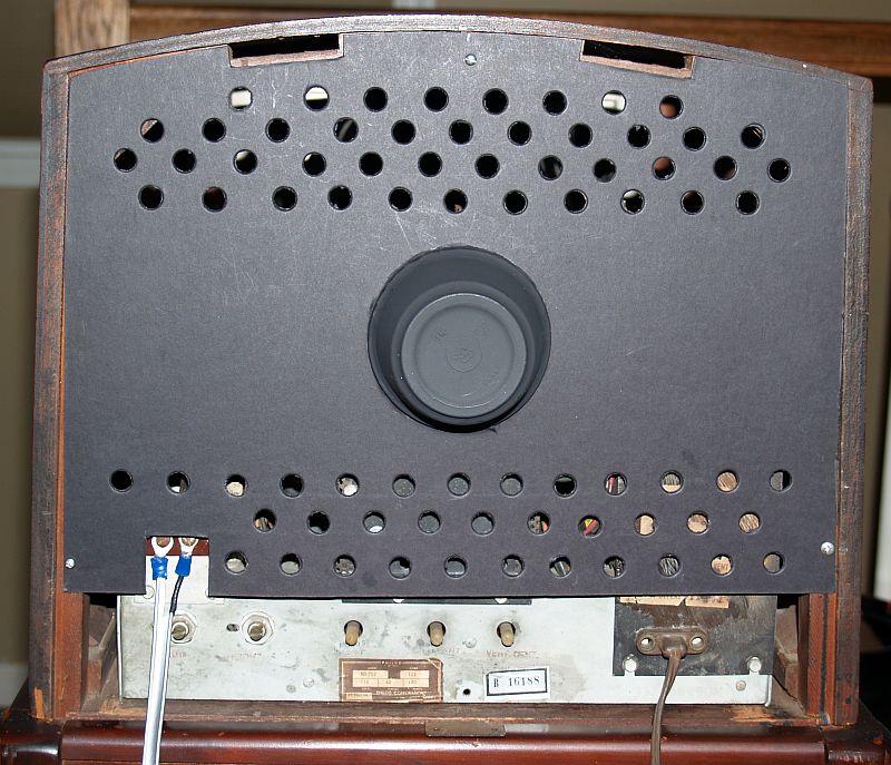
Because the original rear cover was missing, I fabricated a new cover similar to the original using poster board. The new cover is shown below before I installed a cup to protect the neck of the CRT.
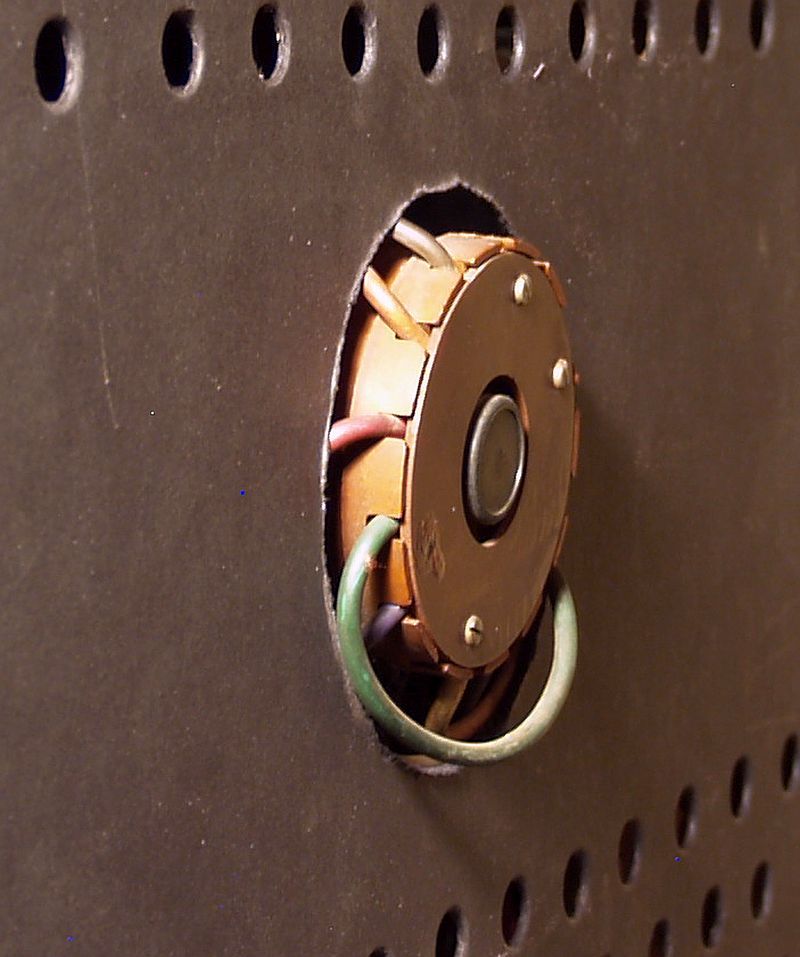
The neck of the CRT extends a bit beyond the cover as shown in the picture below. Thus, a cup that extends beyond the cover is required to protect the CRT.
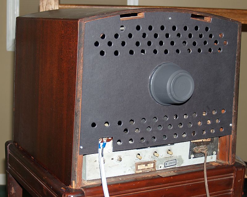
I inserted a plastic cup (made from a yogurt cup) in the hole as a protector for the CRT. I painted the cup black as shown below.
Tube Compliment
The television works well now but the picture is not bright. It is best viewed in low room light. The television does have the brightness fading issue I have read about. After restoration, this television is known for the picture brightness to fade after about 10-20 minutes of operation. My television does seem to somewhat exhibit this problem, although the image is still viewable.
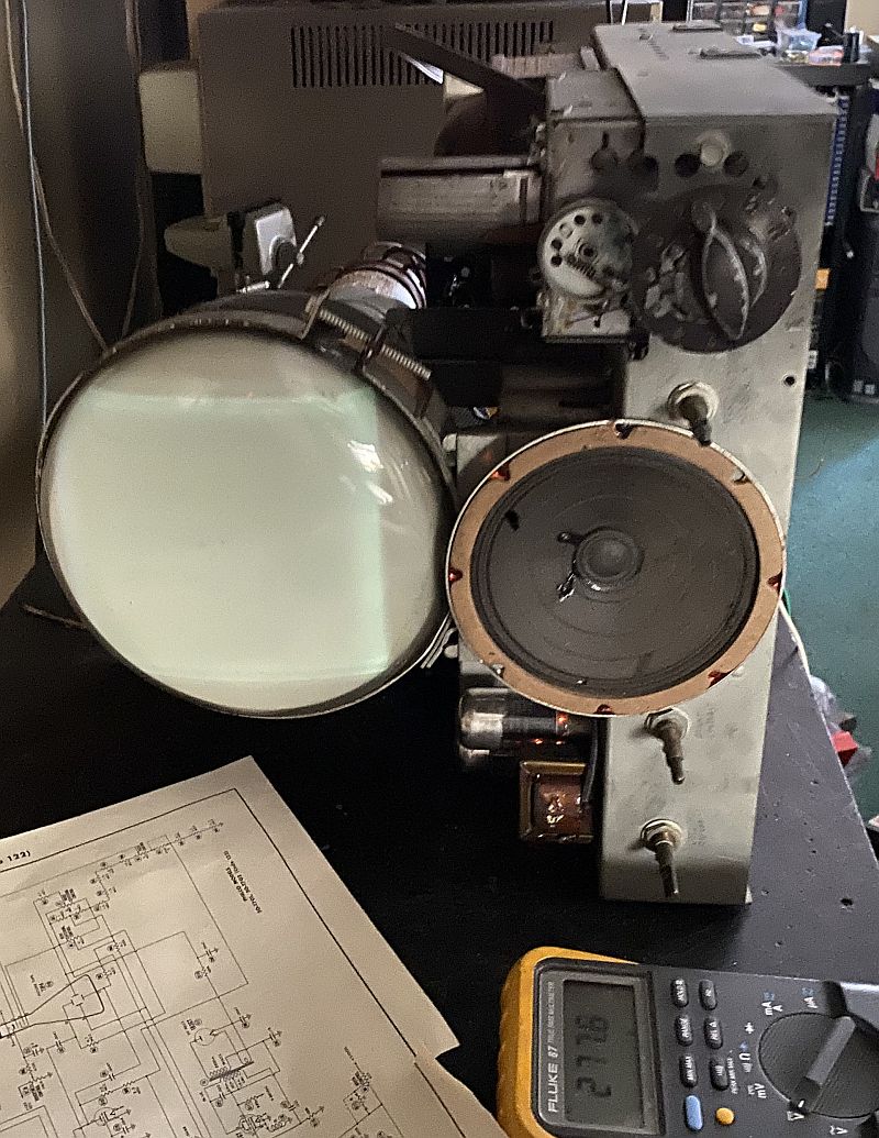
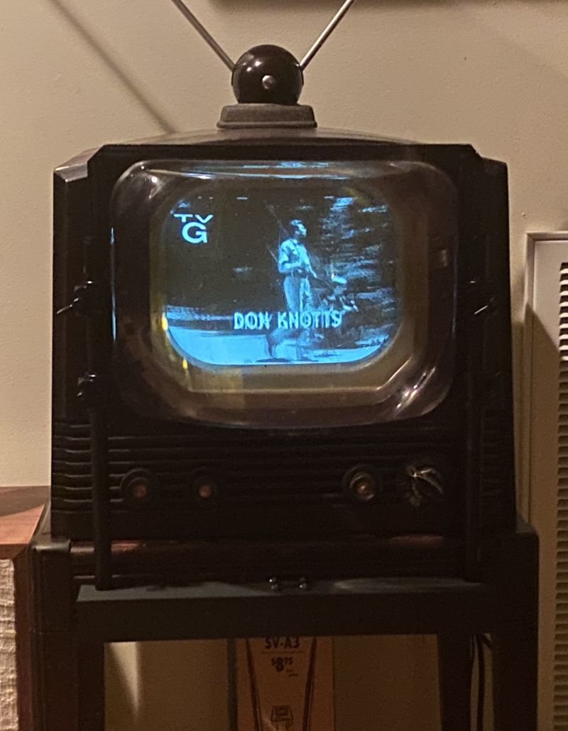
The television seems to work well. I have a Blonder Tongue BAVM-860SAW agile modulator operating on Channel 12 that takes video and audio from a Zenith HDTV-to-analog TV converter box and transmits it across the room and the television receives this transmission via the rabbit ears antenna on top of the set. The agile modulator is shown below.

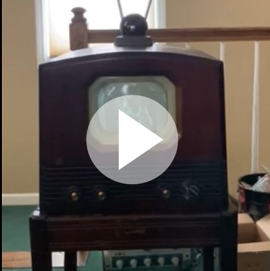
Below is a video of the television operating and receiving a vintage program.
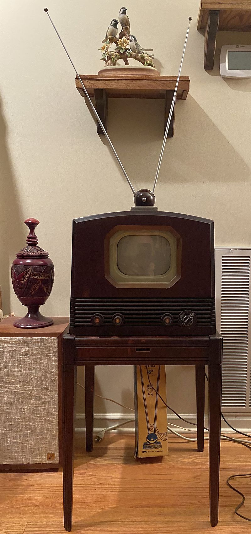
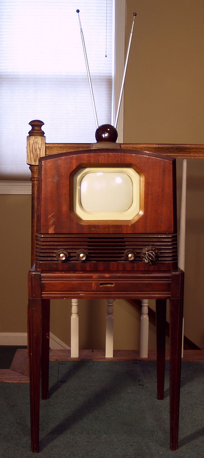
Below is a picture of the television mounted on its original 4-legged stand.
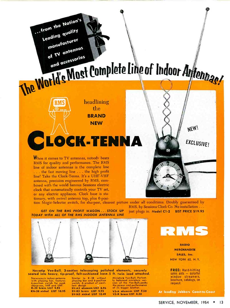
The rabbit ears antenna is vintage, too. A picture of the antenna is shown below.
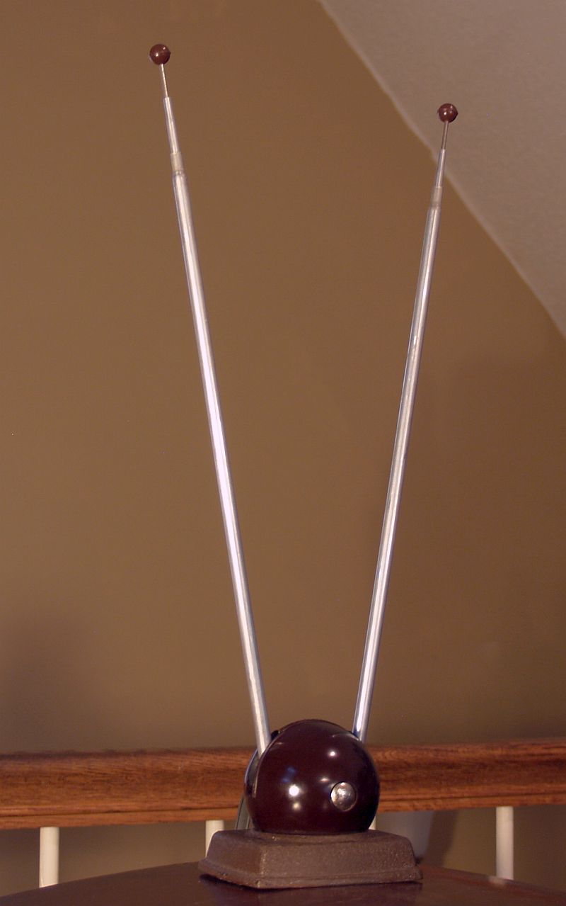
The rabbit ears indoor antenna is Nevatip Vee-Ball 3-section telescoping antenna, Model No. SV-A3 manufactured by Radio Merchandise Sales (RMS) of New York 62, New York. As shown below in the advertisement in the Service Magazine in November 1954, the antenna sold for $8.95.
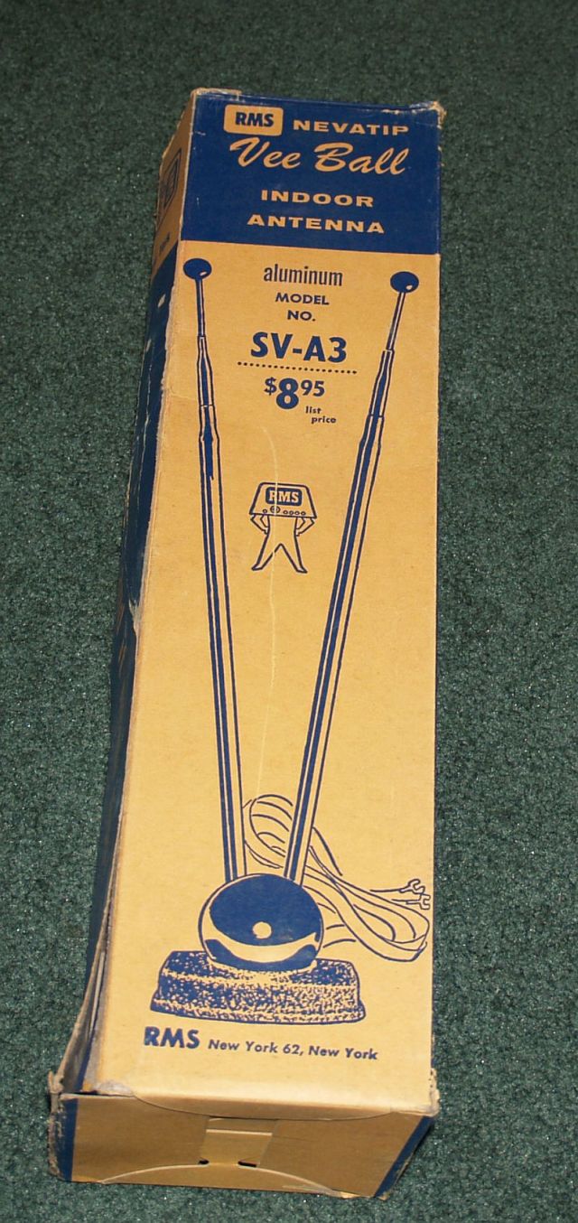
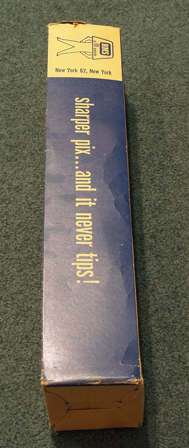
Below is a picture of the original box for the RMS indoor antenna. You can see the price on the box is the same price as the advertisement.
 |
 |
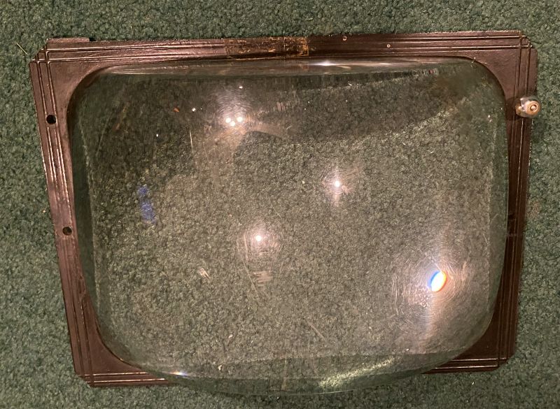
I also have the magnifier for this television. A magnifier was often sold for small-screen televisions to make the image larger. The magnifier is shown below. The magnifier is an oil-filled plastic resevoir.
I do not have the original bended-rod magnifier support nor the devices that mount the magnifier to the rod. The bended-rod magnifier support slides into the slit in the front of the stand to hold the magnifier up in front of the CRT. I made a mount for the magnifier using right angle and sheet aluminumn and camera mounting components. Bleow is a picture of my mount holding the magnifier in front of the television
Below is a picture of a television program seen with the magnifier in place.
Below is video of a television program as seen with the magnifier in place.
I did not refinish the television cabinet or stand. I wanted to preserve the decal on the front of the television. I did rub Howards Feed-N-Wax wood polish and conditioner on the television cabinet and stand to reduce the effects of the scratches and dings. The polish and conditoner also removed the paint specs on the stand.